-40%
RGB/YPbPr Video Kit for Intellivision
$ 18.48
- Description
- Size Guide
Description
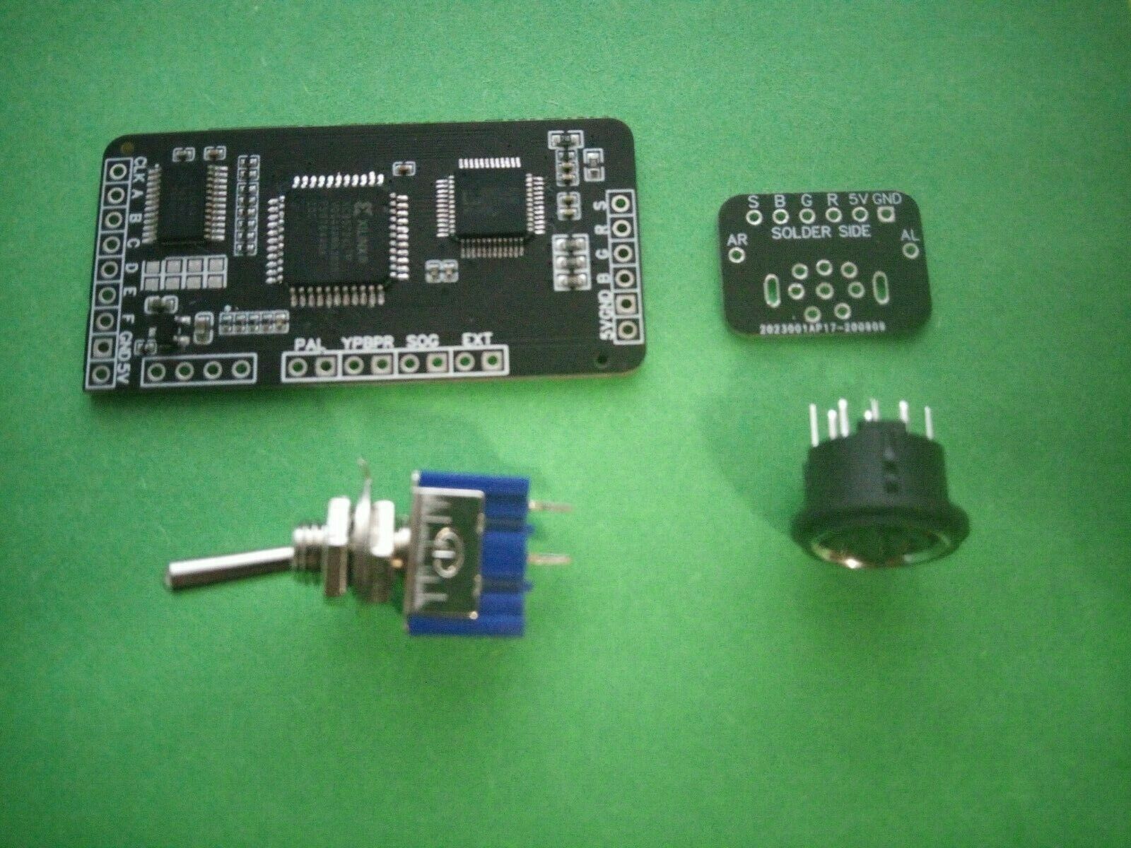
This device when connected to the AY-3-8915 inside NTSC Intellivisions will allow you to put out RGB video or YPbPr video.So far this has been tested and working with Retrotink 2X,
Retrotink 5X
, OSSC, XRGB, CRTs, generic scalers, etc and seems to work across all tests.
This device can also work on PAL consoles (even the ones missing the AY-3-8915) by setting the EXT jumper (discussed below).
These kits will have been tested and played on so any issues will probably come down to user error or TV incompatibility.
The OSSC in 5X mode or on a CRT (YPbPr) is my preferred way to play.
----------------------------------------------------------------------------------------------------------
What Is Included with the Kit:
RGB/YPbPr kit
8 pin mini din (with connector PCB)
One SPST on/off switch (for setting any one of the jumpers [discussed later]
Suggested Items Needed for Installation:
Wire stripper.
Flush cutters.
26-22AWG wire (preferably multicolored [I used Remmington Industries BTW])
Zip ties (for wire neatness)
Something to mount the RGB kit
Some type of adhesive to attach the 8 pin mini din. (epoxy suggested on the model 1).
An adjustable soldering iron.
Flux-cored no clean solder (I use Indium 53563-0454).
A J tip iron tip is preferable when making connections to the 8 pin.
Multimeter for checking pad to pin continuity.
A small file or sandpaper (needed only for the model 2 if placing din connector on back).
A step bit. Otherwise, the diameter of the 8 pin connector is 3/8 inches.
Considerations:
Since the kit and the IC for creating the RF signals share the same inputs; RF may be harmed when installing this kit.
Unlike other video kits, RF may be removed completely if desired (it is not necessary to do this).
Installing this kit incorrectly enough could damage your console or the kit (which I am not responsible for). Take particular care not to mix up ground, 5V, or CLK with each other.
The model 1 should probably have a resistor 12ohm 3 watts (high temp) resistor and 2 transistors (2N3906) replaced. They may burn up and damage the console or kit. (These are not provided).
The model 2 probably needs an audio mod that will disable audio on the RF output.
If RF is not needed you can remove the trace to the RF switch and use that as an additional switch for triggering one of the optional jumpers. (Only do this if you know what you are doing).
Ground is meant to be sent into one end of the kit and taken out of the other for the video outputs. Do not send from the motherboard directly to the video outputs (it will cause noise).
This kit alone should not be used with SEGA-style cables with internal 75-ohm resistors. To use those cables, you would need to remove the resistors in the cable (or do some other workaround). Do not under any circumstance remove the 75 resistors off the kit. If you do use these cables it won't cause any harm; however, the picture will be about twice as dark as normal.
If using a PAL console that is missing the AY-3-8915 then make the connections instead to the AY-3-8900. The AY-3-8900 can be used for NTSC or PAL just FYI.
When in doubt over anything message me.
Jumpers:
There are four through-hole jumpers on the top of the board and 1 solder jumper on the bottom. The jumpers on the top will be two pads next to each other. The square one will be ground and the other will be the pad to be jumpered to ground.
SJ1: This is on the bottom of the board and should be soldered together.
PAL: This can toggle from the default pallet to the alternate pallet. (It has nothing to do with the PAL/NTSC region).
YPbPr: This switches the outputs from RGB to YPbPr. Where R = Ry, G = Y, and B = Pb.
EXT: When you bridge the EXT pads the sync mode will go from NTSC to PAL (NTSC is default).
Since there are two majorly different consoles, I will detail each separately.
Model 1:
Test the console over RF. Confirm it functions over a sufficient period of time.
Locate and remove the 6 screws that hold the console together.
Remove the top shell and set it aside.
Carefully remove connectors going to the power module.
Remove the 6 screws in the plastic bar that holds the PCB/Shield in place.
Lift out the PCB/RF shield. Set the rest of the console aside.
Desoldering the RF Shield:
Begin desoldering the legs that hold on the RF shield.
You may opt to just use a blunt object like a flat head screwdriver and heat and pop the joints.
Save the cart ground connection for last.
Lift top RF shield away.
The bottom shell can be left alone but needs to be removed if you plan to change out transistors or capacitors.
Locate AY-3-8915:
First, find the location of the AY-3-8915 on the top of the PCB.
Locate pin one. This will be indicated be a divot in the IC.
With the location of the IC and pin one in mind flip the board over to the bottom to find pin one again.
Mark pin one or otherwise remember which one it is.
Refer to this picture for the layout of the pins you will be making a connection to:
Attaching Wire:
Cut 8 wires about 6 inches in length. [this can be less if you want to place the kit someplace else]
Strip a small amount off of one end of each wire.
Pre-tin (add a dab of solder) to each of the wire tips.
Cut each tip until each end is the same length (around 1MM).
Add fresh solder to the relevant pins.
Whilst heating the fresh solder place the wire into the solder.
Hold the wire until the solder sets.
Properly set solder should be smooth and have a conical shape.
Don’t forget to locate and attach the wire for audio. [shown in the previous picture]
Keep both the audio line and the CLK pin away from other wires (as much as practical). Particularly keep these noisy lines away from the RGB/YPbPr output wires.
Roughout where you are going to place the kit.
Snake the wires that will be going to the kit to their rough location and cut to length. As before strip and pre-tin about 1mm off the remaining ends.
Attaching the Output connector:
The output connector by default is 8 pin mini din or MD-80SV.
It is deeply recommended to use a step bit to make the desired hole. Gradually increasing the size until the connector fits.
Once the hole is of sufficient size, grab the tiny PCB that pairs with the 8 pin connector.
Locate the side that says “Insert DIN in this side”.
Test fit the connection twisting left and right until the PCB seats with the 8 pin DIN. (this step makes mounting easier.
To avoid getting glue on the connector pins go ahead and marry the two connectors between the console shell.
Solder all of the pins (having a J tip here helps a lot).
Once soldered it is advised to use epoxy over super glue. The model 1 has issues making stable connections with super glue (at least the kind I tried).
Mix the epoxy and apply carefully around the rim (inside the console). While applying it is good to keep pressure on the front of the DIN connector so that it doesn’t pop out and make a mess. I twist while applying to reach the epoxy to areas I can not reach directly with the Q-Tip.
Ensure the connector is positioned straight. If possible, clamp. Otherwise set aside and check occasionally that it hasn’t drifted until the glue sets up.
Using a RGB cable is a decent way to manipulate the position of the connector before the glue sets up.
Attaching Wires to the Kit:
If you have used multicolored wire this part may be easy. Otherwise manually confirm the location of the wire from end to end. Starting from the top left (CLK), and ending at the bottom left (5V).
If you are confident that you have run your inputs correctly you can go ahead and replace the top RF shield.
The output video lines will be run to the right towards the 8 pin mini din or other connectors. To attach wires to each of the ends and clip it when it is a little longer than needed.
After running all the output lines trim them so they are the same length.
Audio will run into a capacitor then spit between both AR and AL. (It is best to do this before the video runs).
Once again cut then pre-tin the end of your wires. Solder the wires in place.
Now you should be able to test to confirm functionality.
If everything is functioning as desired, then you should resolder the RF shield then mount the kit where you have chosen earlier.
Put the console back together in the same order you took it apart.
Model 2:
Test the console over RF. Confirm it functions over a sufficient period of time.
Locate and remove the 2 screws that hold the console together. (PICTURE 1)
Set the top shell and screws aside.
Carefully remove the LED stick. I wiggle it back and forth while pulling up.
Remove the 4 screws that hold the motherboard to the plastic shell. Take not that the 2 screws with the bevel go to the cart slot. Set everything but the motherboard to the side.
Locate AY-3-8915:
First, find the location of the AY-3-8915 on the top of the PCB.
Locate pin one. This will be indicated be a divot in the IC.
With the location of the IC and pin one in mind flip the board over to the bottom to find pin one again.
Mark pin one or otherwise remember which one it is.
Attaching Wire:
Cut 8 wires about 6 inches in length. [this can be less if you want to place the kit someplace else].
Strip a small amount off of one end of each wire.
Pre-tin (add a dab of solder) to each of the wire tips.
Cut each tip till each end is the same length (around 1MM).
Add fresh solder to the relevant pins.
While heating the fresh solder place the wire into the solder.
Hold the wire until the solder sets.
Properly set solder should be smooth and have a conical shape.
Keep both the audio line and the CLK pin away from other wires (as much as practical). Particularly keep these noisy lines (audio and CLK) away from the RGB/YPbPr output wires.
Audio:
Audio on the model 2 is noisy as heck. It has a 120hz hum on the audio line. This hum will likewise produce a hum on the audio output. You can either live with this and send that audio out through a 1UF 25V capacitor, or you can do an audio mod.
For the audio mod (this will disable RF audio) locate the AY-3-8914.
Find pin 3, 4, and 38. Lift these pins.
To lift you can either cut and lift or desolder and lift the pins.
Once lifted take wires and bridge the three lifted pins.
Attach another wire to any of the 3 bridged pins.
Attach one end of that wire to a 1k-5k resistor (higher resistance will be louder).
Attach the other end of the resistor to ground.
The tip where your wire and your resistor meet will need a 1uf 25V capacitor attached to it. (Negative toward the source/positive towards destination).
Finally, attach two jumper wires from the positive leg of the capacitor; This will be AR and AL (audio left and right).
Roughout where you are going to place the kit.
Snake the wires that will be going to the kit to their rough location and cut to length. As before strip and pre-tin about 1mm off the remaining ends.
Attaching Wires to the Kit:
If you have used multicolored wire this part may be easy. Otherwise manually confirm the location of the wire from end to end. Starting from the top left (CLK) and ending at the bottom left (5V).
If you are confident that you have run your inputs correctly you can go ahead and replace the top RF shield.
The output video lines will be run to the right towards the 8 pin mini din or another connector. So attach a wire to each of the ends and clip it when it is a little longer than needed.
After running all the output lines trim them so they are the same length.
Audio will run into a capacitor then spit between both AR and AL. (It is best to do this before the video runs).
Once again cut then pre-tin the end of your wires. Solder the wires in place.
Now you should be able to test to confirm functionality.
If everything is functioning as desired, then you should resolder the RF shield then mount the kit where you have chosen earlier.
Put the console back together in the same order you took it apart.
Troubleshooting:
Troubleshooting all goes back to checking the wiring. Check your wires before doing anything else.
Next check RF. If RF is not working either the cart is not working, or you have made severe errors on your wiring of the wires input to the kit. Remove the input wires and recheck RF. If RF starts working this will confirm the wiring snafu. If RF is still not working then something is probably wrong with the console or the cart. Bridged pins on the AY-3-8915 would be another thing to look out for.
If your colors are wrong but the video is otherwise fine you have switched around your RGB output wires.
If video is present but glitchy then it is likely the inputs are in the wrong order.
If using YPbPr and you have glitchy or no video then it is likely that you forgot to set the jumper to turn it on and are instead sending RGB to your device.
The other items to look out for would be the 2 transistors and 1 resistor on the model 1. These can burn up sporadically.
If you run into any other issues let me know and I can amend this guide.
